Téléphone : 09 83 00 63 69
shopping_cart Panier (0)
[Tuto] Pilotage de moteur triphasé à faible vitesse
Cet article est inspiré du travail de BerryJam -> http://www.berryjam.eu/2015/04/driving-bldc-gimbals-at-super-slow-speeds-with-arduino/
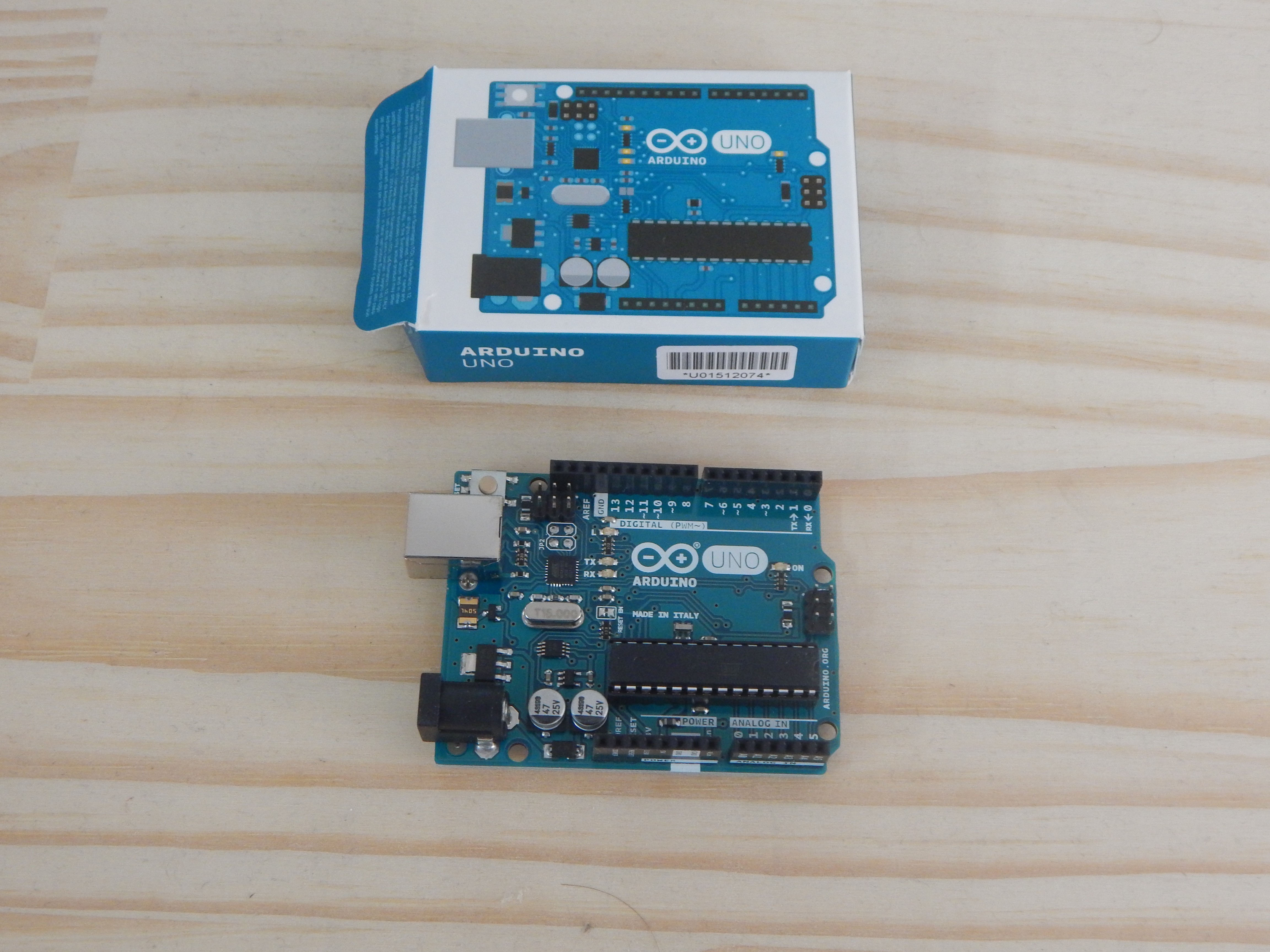
L'objectif de cet article est de piloter un moteur triphasé à l'aide du module driver L6234 conçu par Letmeknow avec un Arduino Uno. Coté câblage, rien de plus simple:
| Module Driver L6234 | Arduino |
| GND | GND |
| IN1 | D9 |
| IN2 | D10 |
| IN3 | D11 |
| EN1 | D5 |
| EN2 | D6 |
| EN3 | D7 |
| PWR | VIN |
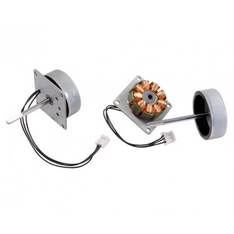
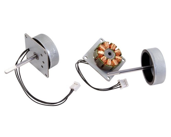
Pour le moteur, on relie simplement les 3 phases sur les 3 broches P1, P2 et P3.

Coté logiciel, on va rester sur le code proposé par BerryJam:
//
// Slow and precise BLDC motor driver using SPWM and SVPWM modulation
// Part of code used from http://elabz.com/
// (c) 2015 Ignas Gramba www.berryjam.eu
//
const int EN1 = 5;
const int EN2 = 6;
const int EN3 = 7;
const int IN1 = 9;
const int IN2 = 10;
const int IN3 = 11;
// SPWM (Sine Wave)
//const int pwmSin[] = {127, 138, 149, 160, 170, 181, 191, 200, 209, 217, 224, 231, 237, 242, 246, 250, 252, 254, 254, 254, 252, 250, 246, 242, 237, 231, 224, 217, 209, 200, 191, 181, 170, 160, 149, 138, 127, 116, 105, 94, 84, 73, 64, 54, 45, 37, 30, 23, 17, 12, 8, 4, 2, 0, 0, 0, 2, 4, 8, 12, 17, 23, 30, 37, 45, 54, 64, 73, 84, 94, 105, 116 };
/// SVPWM (Space Vector Wave)
//const int pwmSin[] = {128, 147, 166, 185, 203, 221, 238, 243, 248, 251, 253, 255, 255, 255, 253, 251, 248, 243, 238, 243, 248, 251, 253, 255, 255, 255, 253, 251, 248, 243, 238, 221, 203, 185, 166, 147, 128, 109, 90, 71, 53, 35, 18, 13, 8, 5, 3, 1, 1, 1, 3, 5, 8, 13, 18, 13, 8, 5, 3, 1, 1, 1, 3, 5, 8, 13, 18, 35, 53, 71, 90, 109};
const int pwmSin[] = {128, 132, 136, 140, 143, 147, 151, 155, 159, 162, 166, 170, 174, 178, 181, 185, 189, 192, 196, 200, 203, 207, 211, 214, 218, 221, 225, 228, 232, 235, 238, 239, 240, 241, 242, 243, 244, 245, 246, 247, 248, 248, 249, 250, 250, 251, 252, 252, 253, 253, 253, 254, 254, 254, 255, 255, 255, 255, 255, 255, 255, 255, 255, 255, 255, 255, 255, 254, 254, 254, 253, 253, 253, 252, 252, 251, 250, 250, 249, 248, 248, 247, 246, 245, 244, 243, 242, 241, 240, 239, 238, 239, 240, 241, 242, 243, 244, 245, 246, 247, 248, 248, 249, 250, 250, 251, 252, 252, 253, 253, 253, 254, 254, 254, 255, 255, 255, 255, 255, 255, 255, 255, 255, 255, 255, 255, 255, 254, 254, 254, 253, 253, 253, 252, 252, 251, 250, 250, 249, 248, 248, 247, 246, 245, 244, 243, 242, 241, 240, 239, 238, 235, 232, 228, 225, 221, 218, 214, 211, 207, 203, 200, 196, 192, 189, 185, 181, 178, 174, 170, 166, 162, 159, 155, 151, 147, 143, 140, 136, 132, 128, 124, 120, 116, 113, 109, 105, 101, 97, 94, 90, 86, 82, 78, 75, 71, 67, 64, 60, 56, 53, 49, 45, 42, 38, 35, 31, 28, 24, 21, 18, 17, 16, 15, 14, 13, 12, 11, 10, 9, 8, 8, 7, 6, 6, 5, 4, 4, 3, 3, 3, 2, 2, 2, 1, 1, 1, 1, 1, 1, 1, 1, 1, 1, 1, 1, 1, 2, 2, 2, 3, 3, 3, 4, 4, 5, 6, 6, 7, 8, 8, 9, 10, 11, 12, 13, 14, 15, 16, 17, 18, 17, 16, 15, 14, 13, 12, 11, 10, 9, 8, 8, 7, 6, 6, 5, 4, 4, 3, 3, 3, 2, 2, 2, 1, 1, 1, 1, 1, 1, 1, 1, 1, 1, 1, 1, 1, 2, 2, 2, 3, 3, 3, 4, 4, 5, 6, 6, 7, 8, 8, 9, 10, 11, 12, 13, 14, 15, 16, 17, 18, 21, 24, 28, 31, 35, 38, 42, 45, 49, 53, 56, 60, 64, 67, 71, 75, 78, 82, 86, 90, 94, 97, 101, 105, 109, 113, 116, 120, 124};
int currentStepA;
int currentStepB;
int currentStepC;
int sineArraySize;
int increment = 0;
boolean direct = 1; // direction true=forward, false=backward
//////////////////////////////////////////////////////////////////////////////

void setup() {
setPwmFrequency(IN1); // Increase PWM frequency to 32 kHz (make unaudible)
setPwmFrequency(IN2);
setPwmFrequency(IN3);
 pinMode(IN1, OUTPUT);
 pinMode(IN2, OUTPUT);
 pinMode(IN3, OUTPUT);
 pinMode(EN1, OUTPUT);
 pinMode(EN2, OUTPUT);
 pinMode(EN3, OUTPUT);
 digitalWrite(EN1, HIGH);
 digitalWrite(EN2, HIGH);
 digitalWrite(EN3, HIGH);
 sineArraySize = sizeof(pwmSin)/sizeof(int); // Find lookup table size
 int phaseShift = sineArraySize / 3; // Find phase shift and initial A, B C phase values
 currentStepA = 0;
 currentStepB = currentStepA + phaseShift;
 currentStepC = currentStepB + phaseShift;
 sineArraySize--; // Convert from array Size to last PWM array number
}
//////////////////////////////////////////////////////////////////////////////

void loop() {
 analogWrite(IN1, pwmSin[currentStepA]);
 analogWrite(IN2, pwmSin[currentStepB]);
 analogWrite(IN3, pwmSin[currentStepC]);
 if (direct==true) increment = 1;
else increment = -1;
 currentStepA = currentStepA + increment;
 currentStepB = currentStepB + increment;
 currentStepC = currentStepC + increment;
 //Check for lookup table overflow and return to opposite end if necessary
 if(currentStepA > sineArraySize) currentStepA = 0;
 if(currentStepA < 0) currentStepA = sineArraySize;
 if(currentStepB > sineArraySize) currentStepB = 0;
 if(currentStepB < 0) currentStepB = sineArraySize;
 if(currentStepC > sineArraySize) currentStepC = 0;
 if(currentStepC < 0) currentStepC = sineArraySize;
 /// Control speed by this delay
 delay(10);
}

void setPwmFrequency(int pin) {
 if(pin == 5 || pin == 6 || pin == 9 || pin == 10) {
 if(pin == 5 || pin == 6) {
 TCCR0B = TCCR0B & 0b11111000 | 0x01;
 } else {
 TCCR1B = TCCR1B & 0b11111000 | 0x01;
 }
 }
 else if(pin == 3 || pin == 11) {
 TCCR2B = TCCR2B & 0b11111000 | 0x01;
 }  }
Pour aller plus loin, vous pouvez joué sur le SVPWM comme dans ce tuto https://electronics-project-hub.com/3-phase-sine-wave-generator-code-arduino/ et piloter la vitesse de votre moteur par un potentiomètre.
//-------www.electronics-project-hub.com--------//
#include "math.h"

int Output1 = 9;
int Output2 = 10;
int Output3 = 11;
const int EN1 = 5;
const int EN2 = 6;
const int EN3 = 7;
int potVal = 0;
float A = 0;
float B = 0.104;
int Freq_IN = A0;
int var1 = 0;
int var2 = 0;
int var3 = 0;
int var4 = 0;
int var5 = 0;
int var6 = 0;
float Phase1 = 2 * PI / 3;
float Phase2 = 4 * PI / 3;
float Phase3 = 2 * PI;
boolean toggle = true; // true = Enabling Serial Plotter Output

void setup()
{
Serial.begin(9600);
 pinMode(Output1, OUTPUT);
 pinMode(Output2, OUTPUT);
 pinMode(Output3, OUTPUT);
 pinMode(Freq_IN, INPUT);
 pinMode(EN1, OUTPUT);
 pinMode(EN2, OUTPUT);
 pinMode(EN3, OUTPUT);
 digitalWrite(EN1, HIGH);
 digitalWrite(EN2, HIGH);
 digitalWrite(EN3, HIGH);
}

void loop()
{
 A += B;
 analogWrite(Output1, var1);
 analogWrite(Output2, var2);
 analogWrite(Output3, var3);
 if (toggle == true)
 {
 Serial.print(var1);
 Serial.print(" ");
 Serial.print(var2);
 Serial.print(" ");
 Serial.println(var3);
 }
 var4 = 126 * sin(A + Phase1);
 var1 = var4 + 128;
 var5 = 126 * sin(A + Phase2);
 var2 = var5 + 128;
 var6 = 126 * sin(A + Phase3);
 var3 = var6 + 128;
 if (A >= 2 * PI)
 {
 A = 0;
 }
 potVal = analogRead(Freq_IN);
 delay(potVal);
}
//-------www.electronics-project-hub.com--------// 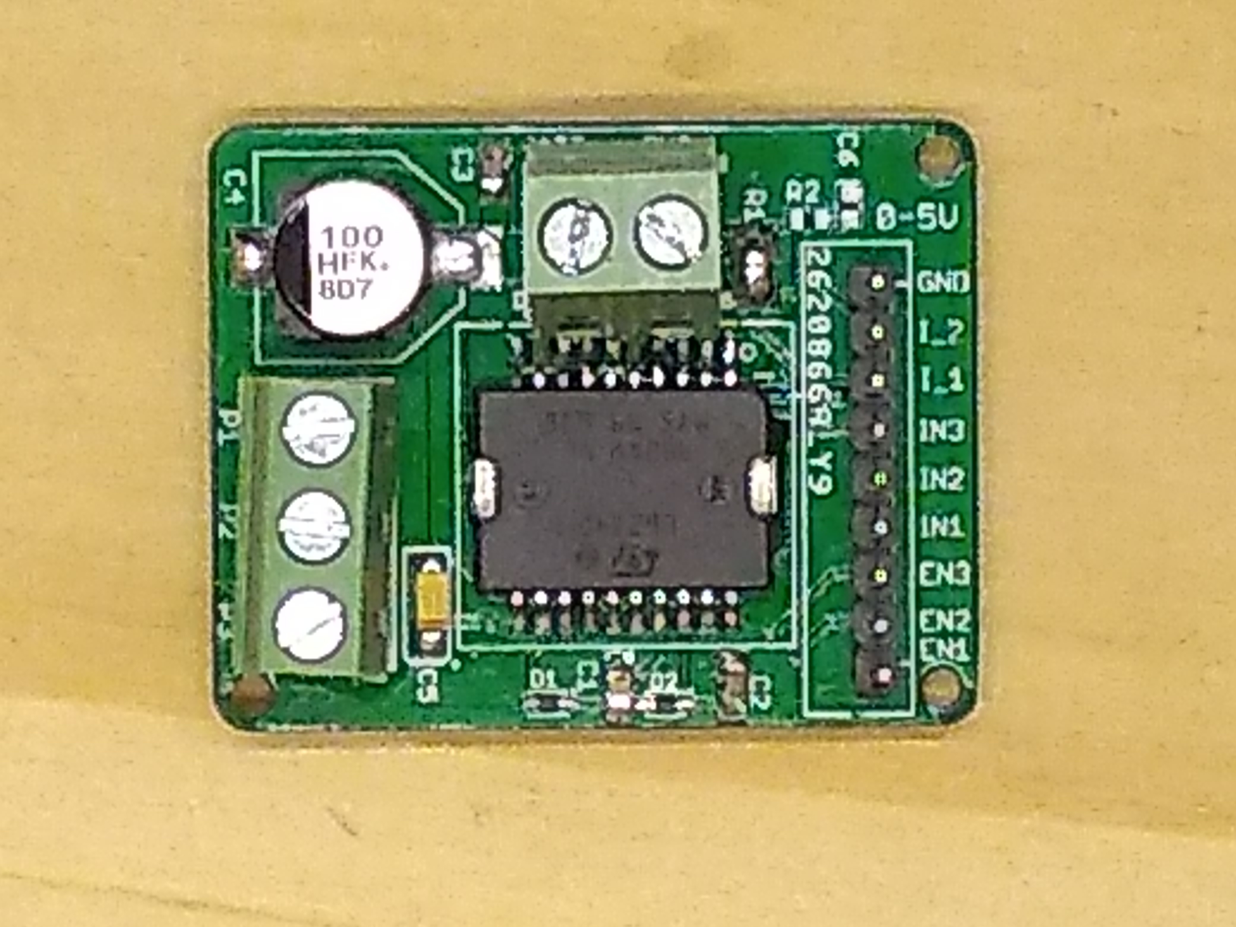
Connectez-vous pour commenter
Se connecter